Connecting the Gantry
The motion controller
The gantry is driven by a separate motion controller board that speaks the grbl protocol over USB serial. The Pi sends G-code; the controller runs the steppers and the electromagnet.
D-40 — Motion control is FluidNC on an ESP32 board with 4$\times$ TMC2209 drivers in UART mode
Context Reducing motor noise and vibration — the gantry equivalent of a 3D printer’s silent mode — requires setting driver current and enabling StealthChop from software. That is only possible if two things hold: the TMC drivers run in UART or SPI mode rather than standalone step/dir, and the firmware can actually speak TMC registers.
Decision FluidNC on an integrated ESP32 board with four TMC2209 sockets pre-wired for UART. This gives software current control, StealthChop and StallGuard, and is right-sized for roughly two motion axes plus an electromagnet.
Rejected Classic GRBL 1.1 cannot address TMC registers at all — with it, run current is a trim potentiometer and StealthChop is a solder jumper, which makes software tuning not merely awkward but impossible. grblHAL can, but its TMC2209 single-wire soft-UART support is documented by its own maintainer as not plug-and-play, with board-specific quirks including an SKR-2 ground-switch MOSFET erratum capable of damaging drivers. The T41U5XBB Teensy grblHAL breakout, which was the earlier lean, turned out on inspection to be a pure STEP/DIR/EN breakout with no driver sockets and no UART line to the drivers — the TMC2209s would have run standalone, defeating the entire purpose.
Consequences Software churn is near zero, because FluidNC still speaks the grbl $ and G-code protocol the existing controller already targets (D-42). The real cost is the configuration model: FluidNC reads driver and pin configuration from a YAML file loaded at boot, not from runtime $-register writes. Run current, hold current, microstepping and StealthChop therefore live in a config file, while motion parameters ($110–$122, $11) remain live writes — so the Kirin-side MotionProfile is partly a config-file generator rather than purely a $x=val emitter. This is a prototyping choice: the shipping product will likely carry a custom motion board.
D-41 — Driver configuration lives in a boot-time YAML file; motion parameters stay live $-writes
Context FluidNC splits its configuration in two: pin mapping and driver setup (current, microstepping, StealthChop) are read from a YAML file at boot, while motion parameters — steps per mm, rates, accelerations — remain runtime $ settings exactly as classic GRBL had them.
Decision Follow that split rather than fighting it. Driver configuration is a file on the controller; tuning stays live over the serial link.
Rejected A pure $x=val emitter, which is what the tuning tooling was before the firmware change. It cannot express the driver settings at all, so keeping that shape would have meant hand-editing the controller’s config out of band and losing the link between a tuning session and the configuration it produced.
Consequences The motion-profile tooling becomes partly a config-file generator, which is a real if modest cost. In exchange, current and StealthChop become software-settable at all — the entire reason for the firmware change (D-40).
D-42 — The controller class and the $/G-code protocol layer are unchanged by the firmware swap
Context Changing motion firmware sounds like it should invalidate the software that drives it.
Decision It does not. FluidNC speaks the same $/G-code protocol the existing controller already targets, so the driving software is untouched.
Rejected Rewriting the controller for a new protocol — there is no new protocol to write for.
Consequences Software churn from the firmware decision was near zero, which is a large part of why the decision was affordable. Worth stating plainly, though: today’s motion controller is a prototyping choice. The product will likely carry a custom motion board, and this protocol seam is what makes that a hardware change rather than a software rewrite.
Note
Everything in the rest of this chapter — the $ settings, the modal G-code setup, the M8/M9 electromagnet control and the coordinate system — is firmware-independent and applies unchanged. Earlier prototypes ran classic GRBL on an Arduino Uno with a CNC shield, and the protocol-level material here was written against that and remains correct.
Serial connection
The controller connects to the Pi via USB and appears as a serial port, usually /dev/ttyUSB0 or /dev/ttyACM0.
# Find the serial port
ls /dev/ttyUSB* /dev/ttyACM*

# Check permissions (your user must be in the 'dialout' group)
groups $USER | grep dialout

# If not in the group:
sudo usermod -aG dialout $USER
# Log out and back in for this to take effect
GRBL Settings
The Kirin software communicates at 115200 baud (GRBL default). Verify the GRBL settings match the physical gantry dimensions. Connect to GRBL with a serial terminal to check:
# Connect with minicom (or screen, picocom, etc.)
minicom -D /dev/ttyUSB0 -b 115200

# In the GRBL console, type:
$$
# This prints all settings
Key settings to verify:
Setting |
Parameter |
Notes |
|---|---|---|
$100 |
X steps/inch |
Must match your stepper + lead screw |
$101 |
Y steps/inch |
Must match your stepper + lead screw |
$110 |
X max rate (in/min) |
Software uses 1000 in/min default |
$111 |
Y max rate (in/min) |
Must be $\geq$ 1000 |
$120 |
X acceleration (in/s$^2$) |
Start with 10, increase after testing |
$121 |
Y acceleration (in/s$^2$) |
Start with 10, increase after testing |
$130 |
X max travel (in) |
Should cover the calibrated command envelope (currently up to X=19.0) |
$131 |
Y max travel (in) |
Should cover the calibrated command envelope (currently up to Y=14.92) |
$22 |
Homing cycle |
Set to 1 (enabled) |
Critical GRBL settings
Electromagnet Control
The electromagnet is controlled through GRBL’s coolant output:
M8= Magnet ON (coolant enable — repurposed for electromagnet)M9= Magnet OFF (coolant disable)
The CNC shield’s coolant enable pin drives a MOSFET or relay that controls the electromagnet. Verify this works before running any game:
# In the GRBL console:
M8     # Magnet should engage
G4 P2.000  # Wait 2 seconds; GRBL P values are seconds
M9     # Magnet should release
Note
Kirin’s dwell(milliseconds) helper accepts milliseconds but emits GRBL seconds. For example, the default pick/release settle time dwell(100) is sent as G4 P0.100. Sending G4 P100 would pause for 100 seconds on GRBL, not 100 milliseconds.
GRBL Motion Mode Setup
After homing, Kirin sends a deterministic modal setup sequence before normal movement:
$H     # Home gantry
G20    # Use inches
G90    # Use absolute coordinates
G94    # Feed rate is units per minute
M9     # Ensure magnet is off
Warning
Do not assume the GRBL controller is already in the correct modal state from a previous session. The software’s coordinate constants and feed rates are expressed in inches and absolute G54 work coordinates, so G20, G90, and G94 must be active before moving pieces.
Physical Coordinate System
The software maps board squares to physical coordinates in inches. The board layout is:
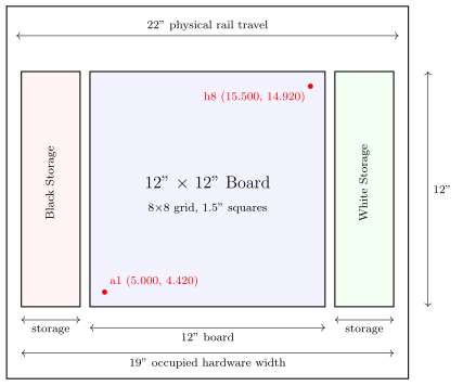
The physical rails are 22” long. The occupied hardware width is 19”: 3” storage + 0.5” gap + 12” board + 0.5” gap + 3” storage. The coordinate system is the calibrated G54 work frame used by Kirin’s normal G1 moves. Square a1 is centered at (5.000”, 4.420”) and each square is 1.5” wide. Ranks advance along +X and files advance along +Y, so h8 is centered at (15.500”, 14.920”). The storage rows use the same 1.5” vertical spacing and align with the board file coordinates.