Wiring the Hall Effect Sensors
Sensor Overview
The system uses 96 A3144 hall effect sensors to detect the presence of magnets embedded in the chess pieces. The sensors are digital (output LOW when a magnet is detected, HIGH when no magnet is present) and require a 10K pull-up resistor each.
The 96 sensors are organized as follows:
Mux |
Coverage |
Channels |
GPIO (SIG) |
|---|---|---|---|
0 |
Black storage zone, left of a-file |
0–15 |
GPIO 4 |
1 |
Board files a–b |
0–15 |
GPIO 7 |
2 |
Board files c–d |
0–15 |
GPIO 8 |
3 |
Board files e–f |
0–15 |
GPIO 9 |
4 |
Board files g–h |
0–15 |
GPIO 10 |
5 |
White storage zone (16 slots) |
0–15 |
GPIO 11 |
Multiplexer assignments
Multiplexer Wiring
All six CD74HC4067 multiplexers share four address/select lines. The Pi sets these four lines (S0–S3) to select a channel (0–15), then reads the SIG output from each mux simultaneously.
Signal Output Lines (Each Mux $\rightarrow$ Pi)
Each mux has a single SIG output that goes to its own GPIO pin on the Pi:
Mux |
SIG $\rightarrow$ Pi GPIO |
Direction |
|---|---|---|
0 |
GPIO 4 |
Input (Pi reads) |
1 |
GPIO 7 |
Input |
2 |
GPIO 8 |
Input |
3 |
GPIO 9 |
Input |
4 |
GPIO 10 |
Input |
5 |
GPIO 11 |
Input |
Signal output wiring
Power and Enable
Connect VCC on each mux to 3.3V (the Pi’s GPIO operates at 3.3V).
Connect GND on each mux to the Pi’s GND.
Connect the EN (enable) pin on each mux to GND (active-low enable, so grounding it keeps the mux always enabled; pin 15 on the bare CD74HC4067 IC).
Warning
Do not power the muxes from 5V. The CD74HC4067 will work at 3.3V, and connecting a 5V signal to the Pi’s GPIO pins can damage the Pi.
Sensor-to-Channel Mapping
Muxes 1–4 scan the 64 board squares. Each board mux covers two adjacent files. Channels 0–7 map to the first file in that pair from rank 8 down to rank 1; channels 8–15 map to the second file in that pair from rank 8 down to rank 1.
Mux |
Files |
Channel Pattern |
|---|---|---|
1 |
a–b |
C0=a8, C1=a7, …, C7=a1; C8=b8, …, C15=b1 |
2 |
c–d |
C0=c8, C1=c7, …, C7=c1; C8=d8, …, C15=d1 |
3 |
e–f |
C0=e8, C1=e7, …, C7=e1; C8=f8, …, C15=f1 |
4 |
g–h |
C0=g8, C1=g7, …, C7=g1; C8=h8, …, C15=h1 |
Board mux channel-to-square mapping
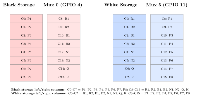
Muxes 0 and 5 scan the storage zones. Mux 0 is black storage to the left of the a-file; mux 5 is white storage to the right of the h-file. Viewed from White’s side, channels 0–7 are the left column top-to-bottom and channels 8–15 are the right column top-to-bottom. That means white storage shows back-rank labels in the left column and pawn labels in the right column, while black storage is visually flipped.
Channel |
Inner Column Slot |
Channel |
Outer Column Slot |
|---|---|---|---|
0 |
R1 |
8 |
P1 |
1 |
R2 |
9 |
P2 |
2 |
B1 |
10 |
P3 |
3 |
B2 |
11 |
P4 |
4 |
N1 |
12 |
P5 |
5 |
N2 |
13 |
P6 |
6 |
Q |
14 |
P7 |
7 |
K |
15 |
P8 |
Storage mux channel-to-slot mapping for both mux 0 and mux 5
Full Board Sensor Map
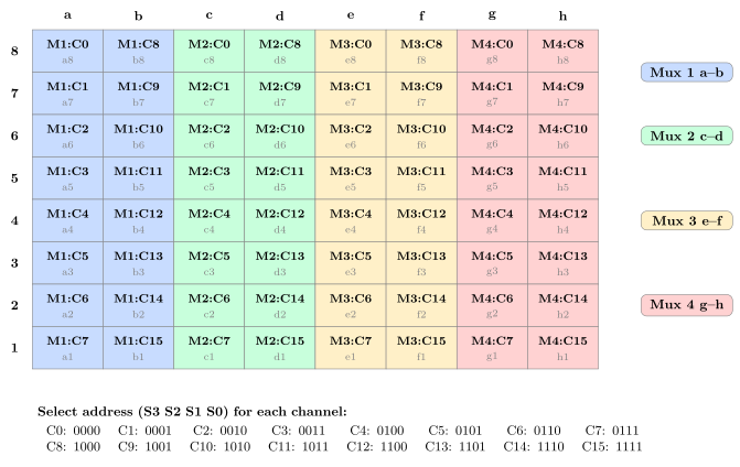
The diagram below shows the complete mapping from every board square to its mux and channel. Each cell shows Mx:Cy where x is the mux number (1–4) and y is the channel (0–15). The mux select address (S3 S2 S1 S0) is shown for each channel on the right.
Storage Zone Sensor Map
The two storage zone muxes each have 16 channels mapped to exact piece storage slots. The black storage zone is left of the a-file on mux 0. The white storage zone is right of the h-file on mux 5. Channels 0–7 are always the visual left column top-to-bottom and channels 8–15 are the visual right column top-to-bottom. White storage therefore maps C0–C7 to R1, R2, B1, B2, N1, N2, Q, K and C8–C15 to P1–P8, while black storage is flipped with C0–C7 = P1–P8 and C8–C15 = R1, R2, B1, B2, N1, N2, Q, K.
Tip
If your physical wiring doesn’t match this channel order, the software’s idea of the board will diverge from the hardware. Either re-wire the sensors to this map or update toSquareIndex() and the storage-slot mapping in board_scanner.cpp.
A3144 Sensor Circuit
Each A3144 sensor has three pins: VCC, GND, and OUTPUT. The output is open-collector, so it needs a pull-up resistor:
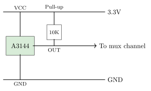
When a magnet is present, the A3144 pulls its output LOW. When no magnet is present, the pull-up resistor holds the output HIGH. The software inverts this logic: LOW = piece present, HIGH = empty.